Fluid power systems are widely used in industrial and mobile applications thanks to some clear advantages in the power transmission, but they also have some critical issues: one of the more concerning nowadays is the low efficiency. Different solutions have been introduced to compensate the gaps for example with installation of electrical equipment or with recovery/regeneration of otherwise wasted energy.
As it is typical a single fluid power generator group, made of a fixed displacement pump driven by an electric motor and a pressure relief valve, is used for multiple purposes, and hence it’s not optimized for a specific application. The energy usage on the actuator side is discontinuous and thus creates high energy waste through the pressure relief valve.
Several possible more efficient alternatives to this simple system already exist, which may be more suitable for the working cycle, i.e. variable displacement pumps with different displacement controls. However, due to different reasons for not replacing the fixed displacement pump (cost, response time, etc.), the idea is to improve the existing system.
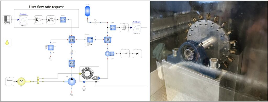
In a scientific paper presented at PHD Symposium della GFPS (Global Fluid Power Society) in October 2022, we studied the possibility to re-transform in mechanical energy that fraction of hydraulic energy that would be wasted by the system through the pressure relief valve. In this way, we can generate a closed loop of power transformation that would help to decrease the absorption at the source.
Because of the discontinuous working phase and the atypical configuration, it was decided to explore the chance to use a Pelton turbine instead of using a positive displacement motor to recover the energy. The design of a Pelton turbine is examined by means of two different standard design methods: the goal of the design is to obtain the best efficiency by appropriate sizing.
The Pelton turbine is coupled to the pump-motor shaft via a reduction drive (the direct connection to the pump shaft is excluded by the design parameters) and the fluid sent to the turbine is first collected in an accumulator with a chosen pre-charged pressure to reduce the irregularities in the flow rate and pressure. An opportune control logic decides when opening the on/off valve that faces the turbine runner and is positioned as the nozzle of the turbine.
After the design of the system, using OpenModelica software and SmartFluidPower Dynamic Library, we created a lumped parameter model of the entire system to validate the concept when working in the real operating conditions. This model is very useful to simulate first the functionality of the hydraulic circuit, in particular the control logic of the accumulator. The second purpose is to analyze both the performance during the operating cycle and the complex dynamic of the system: in fact in just one minute of working there are several injections by the accumulator that opens to the turbine at the reaching of the maximum pressure value. During the injections the turbine feeds power to drive the pump while in the remaining time it acts as a dissipator due to frictions and windage resistance. Setting a batch of simulations we could optimize the parameters of the system to match all requirements and keep the highest performances.
The simulation of the model shows that, despite the amount of losses and resistance caused by the high rotational speed of the turbine, energy recovery is possible. A critical issue on this field may be the erosion of the edge of the bucket due to the jet action because even an erosion of few decimal points of millimetre can be critic for the interface between bucket and fluid. The two turbines have been prototyped and will be tested in the next future by ELT FLUID on the test rig taken as reference for the analysis and, successively, the experimental results will be compared to the simulation.

On the left the dynamic model of the hydraulic system created with the SmartFluidPower library. On the right one of the turbine prototypes built by ELT FLUID.


